This cable will allow the MultiPlus 500VA – 1600VA, MultiPlus Compact 800VA – 2kVA and MultiPlus-II models to be used with BMS products that have no VE.Bus interface, such as the Smart BMS CL 12-100 and the smallBMS. These MultiPlus models can be controlled from the Load/Charge Disconnect outputs and Load/Charger outputs respectively.
The cable must be wired to the remote on/off connector of the MultiPlus models:
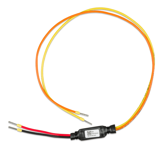
• When used with the MultiPlus 500VA-1200VA models connect the black wire to the ON terminal and the red wire to the (+) terminal.
• When used with the MultiPlus Compact 800VA-2kVA models connect the black wire to the middle terminal and the red wire to the right (IN) terminal.
• When used with the MultiPlus-II models connect the black wire to the lower (-) terminal and the red wire to the upper (+) remote on-off terminal.
Both the Load/Charge Disconnect outputs of Smart BMS CL 12-100 and Load/Charger outputs of the smallBMS must be in ‘High’ state in order for the MultiPlus to operate. After shutdown due to low battery voltage, run the alternator or use a battery charger on the primary side of the BMS to reset the system. The MultiPlus will then switch on and start charging (if connected to an AC power source).
Features
Battery Management system
The BMS connects to 12,8V Victron LiFePO4 (LFP) batteries. Up to 5 batteries may be connected in parallel. Can be used as a system on/off switch.
Alternator and battery protection
The input current is electronically limited to approximately 90% of the fuse rating. A 100A fuse, for example, will therefore limit the input current to approximately 90A.
Choosing the right fuse will:
- a. Protect the LFP battery against excessive charge current (important in case of a low capacity LFP battery).
- b. Protect the alternator against overload in case of a high capacity LFP battery bank (most 12V alternators will overheat and fail if running at maximum output during more than 5 minutes).
Starter battery Protection
This function is similar to that of a Cyrix Battery Combiner or Argo FET Battery Isolator. Current can flow to the LFP battery only if the input voltage (= voltage on the starter battery) exceeds 13V. And current cannot flow back from the LFP battery to the starter battery, thus preventing eventual damage to the LFP battery due to excessive discharge.
Li-ion battery protection
Excessive input voltage and transients are regulated down to a safe level. The Smart BMS CL will stop charging in case of cell over voltage or over temperature. It has three outputs, similar to the miniBMS
Remote on/off input
The remote on/off input controls the charging via the alternator. When off, charging via the alternator is disabled, while the BMS functionality will remain active allowing any loads and chargers to continue working regardless of the state of the remote input. When “system on/off switch” is enabled via VictronConnect, the BMS functionality will also be disabled. It consists of two terminals: Remote L and Remote H. A remote on-off switch or relay contact can be connected between H and L. Alternatively, terminal H can be switched to battery plus, or terminal L can be switched to battery minus
Ignition proof
No relays but MOSFET switches, and therefore no sparks.
CLICK HERE FOR SPEC SHEET